One of The Oldest manufacturers, suppliers & exporter of Stainless Steel Fittings & Flanges, Alloy Steel Fittings & Flanges, Carbon Steel Fittings & Flanges Since 1987.
One of The Oldest manufacturers, suppliers & exporter of Stainless Steel Fittings & Flanges, Alloy Steel Fittings & Flanges, Carbon Steel Fittings & Flanges Since 1987.

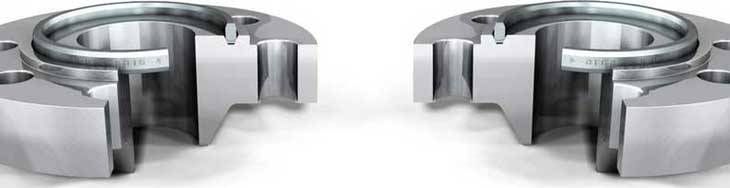
Fitwel Industries LLP is ISO certified organization, which has as extensive & wide range of stock of Ring Type Joint Flange. It can be assembled and disassembled easily with Pipes. The Ring Type Joint Flanges are typically used in high-pressure class 600 and high-temperature services above 800°F. RTJ Flange has grooves cut into their faces which steel ring gaskets. The RTJ flange seal when tightened bolts compress the gasket between the flanges into the grooves, deforming the gasket to make intimate contact inside the grooves, creating a metal to metal seal. An ANSI B16.5 RTJ flange may have a raised face with a ring groove machined into it. This raised face does not serve as any part of the sealing means.
We are one of the pioneer manufacturer, supplier & exporter of high-quality Ring Type Joint Flange ANSI B16.5 Ring Type Joint Fanges, RTJ Flanges, Stainless Steel Ring Type Joint Flanges, Carbon Steel RTJ Flanges, Ring Type Joint, Ring Joint Flanges, Class 150 LBS Ring Type Joint Flanges, BS-4504 RTJ Flanges in Mumbai, Pune, India. We supply our manufactured final products to various Industrial uses in petrochemical, oil, gas and allied industries.
RTJ flanges that seal with ring gaskets, the raised faces of the connected and tightened flanges may contact each other. In this case, the compressed gasket will not bear additional load beyond the bolt tension, vibration and movement cannot further crush the gasket and lessen the connecting tension. As the two Ring Type Joint flange 150 lbs are bolted together and further tightened, the applied bolting force on the flange tends to deform the gaskets inside the flange groove. This is known to create a very tight metal to metal seal. To make this happen, the material of the ring joint gasket has to be softer and more ductile as compared to the material of the Ring Type Joint Flange Raised Face. We also offer these products at custom-made sizes and shapes to our respected clienteles. We Export Ring Type Joint Flanges in Qatar, Kingdom Of Bahrain, Saudi Arabia, Indonesia, United States, Singapore, Malaysia, Turkey, UAE, Russia, Ukraine, South Africa, Australia, etc.
A RTJ Flanges is used when a metal-to-metal seal between the mating flanges is required (which is a condition for high-pressure and high-temperature applications, i.e. above 700/800 C°). A ring joint flange features a circular groove to accommodate a ring joint gasket (oval, or rectangular).
A Ring type joint flange (RTJ) is a machined metallic ring with a deep groove cut into its face. This groove rests a metal ring which gets compressed when the connecting bolts of the flange are tightened. This compression results in a leak-proof, close-fitting seal on the pipe or connection.
RF is raised face flange, which can be used under the pressure of PN1. 6~PN10MPA. FF is flat face flange, which has lower sealability than RF, its pressure is 1.6~2.0MPA (standard: GB9113), and other joint faces like RTJ, FM have higher pressure. The gaskets for RF and FF can be used for each other.
The Ring Type Joint flanges are typically used in high pressure (Class 600 and higher rating) and/or high temperature services above 800°F (427°C). They have grooves cut into their faces which steel ring gaskets. The flanges seal when tightened bolts compress the gasket between the flanges into the grooves, deforming (or Coining) the gasket to make intimate contact inside the grooves, creating a metal to metal seal.
An RTJ flange may have a raised face with a ring groove machined into it. This raised face does not serve as any part of the sealing means. For RTJ flanges that seal with ring gaskets, the raised faces of the connected and tightened flanges may contact each other. In this case the compressed gasket will not bear additional load beyond the bolt tension, vibration and movement cannot further crush the gasket and lessen the connecting tension.
Ring Type Joint gaskets are metallic sealing rings, suitable for high-pressure and high-temperature applications. They are always applied to special, accompanying flanges which ensure good, reliable sealing with the correct choice of profiles and material.
Ring Type Joint gaskets are designed to seal by "initial line contact" or wedging action between the mating flange and the gasket. By applying pressure on the seal interface through bolt force, the "softer" metal of the gasket flows into the microfine structure of the harder flange material, and creating a very tight and efficient seal.
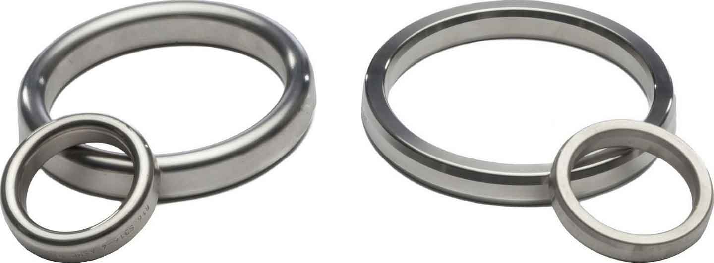
Most applied type is style R ring that is manufactured in accordance with ASME B16.20 used with ASME B16.5 flanges, class 150 to 2500. Style 'R' ring type joints are manufactured in both oval and octagonal configurations.
The Octagonal ring has a higher sealing efficiency than the oval and would be the preferred gasket. However, only the oval cross section can be used in the old type round bottom groove. The newer flat bottom groove design will accept either the oval or the octagonal cross section.
Style R ring type joints are designed to seal pressure up to 6,250 psi in accordance with ASME B16.5 pressure ratings and up to 5,000 psi.
The RX type is suitable for pressures up to 700 bar. This RTJ is capable of sealing itself. The outer sealing surfaces make the first contact with the flanges. A higher system pressure causes a higher surface pressure. Type RX is interchangeable with the standard R-models.
The BX type is suitable for very high pressures up to 1500 bar. This ring joint is not interchangeable with other types, and is only suited for API type BX flanges and grooves.
The sealing surfaces on the ring joint grooves must be smoothly finished to 63 Microinches and be free of objectionable ridges, tool or chatter marks. They seal by an initial line contact or a wedging action as the compressive forces are applied. The hardness of the ring should always be less than the hardness of the flanges.
The table below indicates the most commonly used materials for ring type joints.
General flange faces such as the RTJ, TandG and the FandM shall never be bolted together. The reason for this is that the contact surfaces do not match and there is no gasket that has one type on one side and another type on the other side.
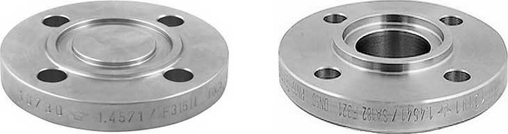
With this type the flanges also must be matched. One flange face has an area that extends beyond the normal flange face (Male). The other flange or mating flange has a matching depression (Female) machined into it's face.
The female face is 3/16-inch deep, the male face is1/4-inch high, and both are smooth finished. The outer diameter of the female face acts to locate and retain the gasket. In principle 2 versions are available; the Small M&F Flanges and the Large M&F Flanges. Custom male and female facings are commonly found on the Heat Exchanger shell to channel and cover flanges.
Better sealing properties, more precise location and exact compression af sealing material, utilization of other, more suitable sealing and spezialized sealing material (O-rings).
Commercial availabillity and cost. Normal raised faced is far more common and ready available both regarding Valves, flanges and sealing material. Another complexity is that some rigid rules must be applied to the piping design. Do you order Valves to be female end both sides, or on one side maybe, in which case do you point all male ends in the flow direction, or what. Same applies to any flanged joint / vessel connection of course.
Standard : ANSI B16.5, ANSI B16.47 Series A & B, MSS SP44, ASA, API-605, AWWA, Custom Drawings
Size : 1 / 8” to 84”NB
Class : 150 LBS, 300 LBS, 600 LBS, 900 LBS, 1500 LBS, 2500 LBS, DIN Standard ND-6,10, 16, 25, 40 Etc.
Flange Face Type : Flate Face (FF), Raised Face (RF), Ring Type Joint (RTJ)
BS : BS4504 , BS4504, BS1560, BS10
DIN : DIN2527, DIN2566, DIN2573, DIN2576, DIN2641, DIN2642, DIN2655, DIN2656, DIN2627, DIN2628, DIN2629, DIN 2631, DIN2632, DIN2633, DIN2634, DIN2635, DIN2636 DIN2637, DIN2638, DIN2673
Specifications for RTJ Flanges is mentioned below. If any of the specification is not mentioned here, please get in touch with us
| Material of Construction | Standard | Grades |
| Stainless Steel RTJ Flanges | ASTM A182 , A240 | F 304, 304L, 304H, 316, 316Ti, 316H, 316L, 316LN, 309S, 309H, 310S, 310H,317, 317L, 321, 321H, 347, 347H, 201, 202, 904L |
| Carbon Steel RTJ Flanges | ASTM A105 | Gr. F42,46,52,56,60,65,70 |
| Alloy Steel RTJ Flanges |
ASTM A182 | F1,F5,F9,F11,F22,F91 |
| Nickel Alloy RTJ Flanges |
ASTM SB564, SB160, SB472, SB162 | Nickel 200 (UNS No. N02200), Nickel 201 (UNS No. N02201), Monel 400 (UNS No. N04400), Monel 500 (UNS No. N05500), Inconel 800 (UNS No. N08800), Inconel 825 (UNS No. N08825), Inconel 600 (UNS No. N06600), Inconel 625 (UNS No. N06625), Inconel 601 (UNS No. N06601), Hastelloy C 276 (UNS No. N10276), Alloy 20 (UNS No. N08020), |
| Copper Alloys RTJ Flanges | ASTM SB 61 , SB62 , SB151 , SB152 | UNS No. C 70600 (Cu-Ni 90/10), C 71500 (Cu-Ni 70/30), UNS No. C 10100, 10200, 10300, 10800, 12000, 12200, |
| Low Temperature Carbon Steel RTJ Flanges | ASTM A350 | LF2 , LF3 |
| Duplex Steel RTJ Flanges | ASTM A182, A240 | UNS F 44, F 45, F51, F 53, F 55, F 60, F 61 |
Dimenion Chart for RTJ Flanges is mentioned below. If any of the Dimension is not mentioned here, please get in touch with us
| Outside Diameter ≤ 24 = 1.6 mm | > 24 = ± 3.2 mm |
Inside Diameter ≤ 10 = ± 0.8 mm | ≥ 12 = + 1.6 mm / – 0 mm |
| Diameter of Contact Face 1.6 mm Raised Face = ± 0.8 mm 6.35 mm Raised Face, Tongue & Groove / Male-Female = ± 0.4 mm |
Outside Diameter of Hub ≤ 12 = + 2.4 mm / – 1.6 mm | ≥ 14 = ± 3.2 mm |
| Diameter of Counterbore Same as for Inside Diameter |
Drilling Bolt Circle = 1.6 mm | Bolt Hole Spacing = ± 0.8 mm Eccentricity of Bolt Circle with Respect to Facing ≤ 2½ = 0.8 mm max. | ≥ 3 = 1.6 mm max. |
| Thickness ≤ 18 = + 3.2 mm / – 0 | ≥ 20 = + 4.8 mm / – 0 |
Length thru Hub ≤ 18 = + 3.2 mm / – 0.8 mm | ≥ 20 = + 4.8 mm / – 1.6 mm |
| R No |
Dia P |
Width A |
Height | Oct C |
Oct R1 |
NPS CL |
|
| Oval B |
Oct H |
||||||
| R 11 | 34.14 | 6.35 | 11.2 | 9.7 | 4.32 | 1.5 | 1/2 300 600 |
| R 12 | 39.7 | 7.95 | 14.2 | 12.7 | 5.23 | 1.5 | 1/2 900 1500 |
| R 13 | 42.88 | 7.95 | 14.2 | 12.7 | 5.23 | 1.5 | 3/4 300 600 1/2 2500 |
| R 14 | 44.45 | 7.95 | 14.2 | 12.7 | 5.23 | 1.5 | 3/4 900 1500 |
| R 15 | 47.63 | 7.95 | 14.2 | 12.7 | 5.23 | 1.5 | 1 150 |
| R 16 | 50.8 | 7.95 | 14.2 | 12.7 | 5.23 | 1.5 | 1 300 1500 3/4 2500 |
| R 17 | 57.15 | 7.95 | 14.2 | 12.7 | 5.23 | 1.5 | 1¼ 150 |
| R 18 | 60.33 | 7.95 | 14.2 | 12.7 | 5.23 | 1.5 | 1¼ 300 1500 1 2500 |
| R 19 | 65.1 | 7.95 | 14.2 | 12.7 | 5.23 | 1.5 | 1½ 150 |
| R 20 | 68.28 | 7.95 | 14.2 | 12.7 | 5.23 | 1.5 | 1½ 300 1500 |
| R 21 | 72.24 | 11.13 | 17.5 | 16 | 7.75 | 1.5 | 1¼ 2500 |
| R 22 | 82.55 | 7.95 | 14.2 | 12.7 | 5.23 | 1.5 | 2 150 |
| R 23 | 82.55 | 11.13 | 17.5 | 16 | 7.75 | 1.5 | 2 300 600 1½ 2500 |
| R 24 | 95.25 | 11.13 | 17.5 | 16 | 7.75 | 1.5 | 2 900 1500 |
| R 25 | 101.6 | 7.95 | 14.2 | 12.7 | 5.23 | 1.5 | 2½ 150 |
| R 26 | 101.6 | 11.13 | 17.5 | 16 | 7.75 | 1.5 | 2½ 300 600 2 2500 |
| R 27 | 107.95 | 11.13 | 17.5 | 16 | 7.75 | 1.5 | 2½ 900 1500 |
| R 28 | 111.13 | 12.7 | 19.1 | 17.5 | 8.66 | 1.5 | 2½ 2500 |
| R 29 | 114.3 | 7.95 | 14.2 | 12.7 | 5.23 | 1.5 | 3 150 |
| R 30 * |
117.48 | 11.13 | 17.5 | 16 | 7.75 | 1.5 | 3 300 600 |
| R 31 | 123.83 | 11.13 | 17.5 | 16 | 7.75 | 1.5 | 3 300 900 |
| R 32 | 127 | 12.7 | 19.1 | 17.5 | 8.66 | 1.5 | 3 2500 |
| R 33 | 131.78 | 7.95 | 14.2 | 12.7 | 5.23 | 1.5 | 3½ 150 |
| R 34 | 131.78 | 11.13 | 17.5 | 16 | 7.75 | 1.5 | 3½ 300 600 |
| R 35 | 136.53 | 11.13 | 17.5 | 16 | 7.75 | 1.5 | 3 1500 |
| R 36 | 149.23 | 7.95 | 14.2 | 12.7 | 5.23 | 1.5 | 4 150 |
| R 37 | 149.23 | 11.13 | 17.5 | 16 | 7.75 | 1.5 | 4 300 900 |
| R 38 | 157.18 | 15.88 | 22.4 | 20.6 | 10.49 | 1.5 | 4 2500 |
| R 39 | 161.93 | 11.13 | 17.5 | 16 | 7.75 | 1.5 | 4 1500 |
| R 40 | 171.45 | 7.95 | 14.2 | 12.7 | 5.23 | 1.5 | 5 150 |
| R 41 | 180.98 | 11.13 | 17.5 | 16 | 7.75 | 1.5 | 5 300 900 |
| R 42 | 190.5 | 19.05 | 25.4 | 23.9 | 12.32 | 1.5 | 5 2500 |
| R 43 | 193.68 | 7.95 | 14.2 | 12.7 | 5.23 | 1.5 | 6 150 |
| R 44 | 193.68 | 11.13 | 17.5 | 16 | 7.75 | 1.5 | 5 1500 |
| R 45 | 211.15 | 11.13 | 17.5 | 16 | 7.75 | 1.5 | 6 300 900 |
| R 46 | 211.15 | 12.7 | 19.1 | 17.5 | 8.66 | 1.5 | 6 1500 |
| R 47 | 228.6 | 19.05 | 25.4 | 23.9 | 12.32 | 1.5 | 6 2500 |
| R 48 | 247.65 | 7.95 | 14.2 | 12.7 | 5.23 | 1.5 | 8 150 |
| R 49 | 269.88 | 11.13 | 17.5 | 16 | 7.75 | 1.5 | 8 300 900 |
| R 50 | 269.88 | 15.88 | 22.4 | 20.6 | 10.49 | 1.5 | 8 1500 |
| R 51 | 279.4 | 22.23 | 28.7 | 26.9 | 14.81 | 1.5 | 8 2500 |
| R 52 | 304.8 | 7.95 | 14.2 | 12.7 | 5.23 | 1.5 | 10 150 |
| R 53 | 323.85 | 11.13 | 17.5 | 16 | 7.75 | 1.5 | 10 300 900 |
| R 54 | 323.85 | 15.88 | 22.4 | 20.6 | 10.49 | 1.5 | 10 1500 |
| R 55 | 342.9 | 28.58 | 36.6 | 35.1 | 19.81 | 2.3 | 10 2500 |
| R 56 | 381 | 7.95 | 14.2 | 12.7 | 5.23 | 1.5 | 12 150 |
| R 57 | 381 | 11.13 | 17.5 | 16 | 7.75 | 1.5 | 12 300 900 |
| R 58 | 381 | 22.23 | 28.7 | 26.9 | 14.81 | 1.5 | 12 1500 |
| R 59 | 396.88 | 7.95 | 14.2 | 12.7 | 5.23 | 1.5 | 14 150 |
| R 60 | 406.4 | 31.75 | 39.6 | 38.1 | 22.33 | 2.3 | 12 2500 |
| R 61 | 419.1 | 11.13 | 17.5 | 16 | 7.75 | 1.5 | 14 300 600 |
| R 62 | 419.1 | 15.88 | 22.4 | 20.6 | 10.49 | 1.5 | 14 900 |
| R 63 | 419.1 | 25.4 | 33.3 | 31.8 | 17.3 | 2.3 | 14 1500 |
| R 64 | 454.03 | 7.95 | 14.2 | 12.7 | 5.23 | 1.5 | 16 150 |
| R 65 | 469.9 | 11.13 | 17.5 | 16 | 7.75 | 1.5 | 16 300 600 |
| R 66 | 469.9 | 15.88 | 22.4 | 20.6 | 10.49 | 1.5 | 16 900 |
| R 67 | 469.9 | 28.58 | 36.6 | 35.1 | 19.81 | 2.3 | 16 1500 |
| R 68 | 517.53 | 7.95 | 14.2 | 12.7 | 5.23 | 1.5 | 18 150 |
| R 69 | 533.4 | 11.13 | 17.5 | 16 | 7.75 | 1.5 | 18 300 600 |
| R 70 | 533.4 | 19.05 | 25.4 | 23.9 | 12.32 | 1.5 | 18 900 |
| R 71 | 533.4 | 28.58 | 36.6 | 35.1 | 19.81 | 2.3 | 18 1500 |
| R 72 | 558.8 | 7.95 | 14.2 | 12.7 | 5.23 | 1.5 | 20 150 |
| R 73 | 584.2 | 12.7 | 19.1 | 17.5 | 8.66 | 1.5 | 20 300 600 |
| R 74 | 584.2 | 19.05 | 25.4 | 23.9 | 12.32 | 1.5 | 20 900 |
| R 75 | 584.2 | 31.75 | 39.6 | 38.1 | 22.33 | 2.3 | 20 1500 |
| R 76 | 673.1 | 7.95 | 14.2 | 12.7 | 5.23 | 1.5 | 24 150 |
| R 77 | 692.15 | 15.88 | 22.4 | 20.6 | 10.49 | 1.5 | 24 300 600 |
| R 78 | 692.15 | 25.4 | 33.3 | 31.8 | 17.3 | 2.3 | 24 900 |
| R 79 | 692.15 | 34.93 | 44.5 | 41.4 | 24.82 | 2.3 | 24 1500 |
| R No |
Dia P |
Width A |
Height | Oct C |
Oct R1 |
NPS CL |
|
| Oval B |
Oct H |
||||||
| R 93 | 749.3 | 19.05 | 23.9 | 12.32 | 1.5 | 26 300 600 |
|
| R 94 | 800.1 | 19.05 | 23.9 | 12.32 | 1.5 | 28 300 600 |
|
| R 95 | 857.25 | 19.05 | 23.9 | 12.32 | 1.5 | 30 300 600 |
|
| R 96 | 914.4 | 22.23 | 26.9 | 14.81 | 1.5 | 32 300 600 |
|
| R 97 | 965.2 | 22.23 | 26.9 | 14.81 | 1.5 | 34 300 600 |
|
| R 98 | 1022.35 | 22.23 | 26.9 | 14.81 | 1.5 | 36 300 600 |
|
| R 100 | 749.3 | 28.58 | 35.1 | 19.81 | 2.3 | 26 900 |
|
| R 101 | 800.1 | 31.75 | 38.1 | 22.33 | 2.3 | 28 900 |
|
| R 102 | 857.25 | 31.75 | 38.1 | 22.33 | 2.3 | 30 900 |
|
| R 103 | 914.4 | 31.75 | 38.1 | 22.33 | 2.3 | 32 900 |
|
| R 104 | 965.2 | 34.93 | 41.4 | 24.82 | 2.3 | 34 900 |
|
| R 105 | 1022.35 | 34.93 | 41.4 | 24.82 | 2.3 | 36 900 |
|
All dimensions are in millimeters.
P = average pitch diameter of ring ±0.18
A = width of ring ±0.20
B & H = height of ring +1.3. -0.5
Variation in height throughout the entire circumference of any given ring shall not exceed 0.5 within these tolerances
C = width of flat on octagonal ring ±0.20
R1 = radius in ring ±0.5
23 ° = angle ±0 ° 30 min
*R-30 = for lapped joint only
Other Related Products:

Oil & Gas Industries

Petrochemical Industries

Engineering Industries

Chemical Industries
Sugar Industries

Power Generation Industries

Fertilizers Industries

Food Processing Industries